ADT7518
Rev. A | Page 25 of 40
5. Place 0.1 礔 bypass and 2,200 pF input filter capacitors
close to the ADT7518.
6. If the distance to the remote sensor is more than 8 inches,
the use of twisted-pair cable is recommended. This will
work up to about 6 feet to 12 feet.
7. For long distances (up to 100 feet), use shielded twisted-
pair cable, such as Belden #8451 microphone cable.
Connect the twisted pair to D+ and D and the shield to
GND close to the ADT7518. Leave the remote end of the
shield unconnected to avoid ground loops.
Because the measurement technique uses switched current
sources, excessive cable and/or filter capacitance can affect the
measurement. When using long cables, the filter capacitor may
be reduced or removed.
Cable resistance can also introduce errors. Series resistance of
1 & introduces about 0.5癈 error.
Temperature Value Format
One LSB of the ADC corresponds to 0.25癈. The ADC can
theoretically measure a temperature span of 255癈. The internal
temperature sensor is guaranteed to a low value limit of 40癈.
It is possible to measure the full temperature span using the
external temperature sensor. The temperature data format is
shown in Table 9.
The result of the internal or external temperature measure-
ments is stored in the temperature value registers, and is com-
pared with limits programmed into the internal or external high
and low registers.
Table 9. Temperature Data Format (Internal and External
Temperature)
Temperature
Digital Output
40癈
11 0110 0000
25癈
11 1001 1100
10癈
11 1101 1000
0.25癈
11 1111 1111
0癈
00 0000 0000
+0.25癈
00 0000 0001
+10癈
00 0010 1000
+25癈
00 0110 0100
+50癈
00 1100 1000
+75癈
01 0010 1100
+100癈
01 1001 0000
+105癈
01 1010 0100
+125癈
01 1111 0100
Temperature Conversion Formula:
Positive Temperature = ADC Code/4
Negative Temperature = (ADC Code* 512)/4
*where DB9 is removed from the ADC code.
Interrupts
The measured results from the internal temperature sensor,
external temperature sensor, VDD pin, and AIN inputs are
compared with the THIGH/VHIGH (greater than comparison) and
TLOW/VLOW (less than or equal to comparison) limits. An inter-
rupt occurs if the measurement exceeds or equals the limit
registers. These limits are stored in on-chip registers. Note that
the limit registers are 8 bits long while the conversion results are
10 bits long. If the limits are not masked, any out-of-limit com-
parisons generate flags that are stored in the Interrupt Status 1
register (Address 00h) and Interrupt Status 2 register
(Address 01h). One or more out-of-limit results will cause the
INT/INT
output to pull either high or low depending on the
output polarity setting. It is good design practice to mask out
interrupts for channels that are of no concern to the application.
Figure 49 shows the interrupt structure for the ADT7518. It
gives a block diagram representation of how the various
measurement channels affect the INT/INT
pin.
ADT7518 REGISTERS
The ADT7518 contains registers that are used to store the
results of external and internal temperature measurements, V
DD
value measurements, analog input measurements, high and low
temperature limits, supply voltage and analog input limits, to set
output DAC voltage levels, to configure multipurpose pins, and
generally to control the device. A description of these registers
follows.
The register map is divided into registers of 8 bits. Each register
has its own individual address, but some consist of data that is
linked to other registers. These registers hold the 10-bit conver-
sion results of measurements taken on the temperature, V
DD
,
and AIN channels. For example, the eight MSBs of the VDD
measurement are stored in Register Address 06h, while the two
LSBs are stored in Register Address 03h. These types of registers
are linked such that when the LSB register is read first, the MSB
registers associated with that LSB register are locked to prevent
any updates. To unlock these MSB registers, the user has only to
read any one of them, which will have the effect of unlocking all
previously locked MSB registers. So, for the preceding example,
if Register 03h was read first, MSB Registers 06h and 07h would
be locked to prevent any updates to them. If Register 06h were
read, this register and Register 07h would be subsequently
unlocked.
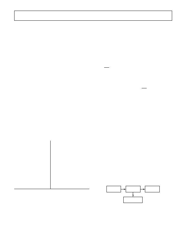
LOCK ASSOCIATED
MSB REGISTERS
FIRST READ
COMMAND
LSB
REGISTER
OUTPUT
DATA
Figure 51. Phase 1 of 10-Bit Read
发布紧急采购,3分钟左右您将得到回复。
相关PDF资料
AT30TS00-MAH-T
SENSOR DGTL TEMP I2C/SMBUS 8WDFN
AT30TSE002B-MAH-T
SENSOR DGTL TEMP I2C/SMBUS 8WDFN
BD3504FVM-TR
IC REG CTRLR SGL POS ADJ 8MSOP
BD3521FVM-TR
IC REG CTRLR SGL 1.5V MSOP8
BD9153MUV-E2
IC REG TRPL BCK/LINEAR 24VQFN
CAT2300VP2-GT3
IC SENSE FET CONTROLLER 8TDFN
CAT34TS02VP2GT4A
IC TEMP SENSOR 2K MEMORY 8TDFN
CAT6095VP2-GT4
IC TEMP SENSOR STAND ALONE 8TDFN
相关代理商/技术参数
ADT7518ARQZ-REEL
制造商:Analog Devices 功能描述:Temp Sensor Analog Serial (4-Wire, SPI, I2C) 16-Pin QSOP T/R
ADT7518ARQZ-REEL7
制造商:Analog Devices 功能描述:Temp Sensor Analog Serial (4-Wire, SPI, I2C) 16-Pin QSOP T/R
ADT7519
制造商:AD 制造商全称:Analog Devices 功能描述:SPI-/I2C-Compatible, Temperature Sensor,4-Channel ADC and Quad Voltage Output
ADT7519ARQ
制造商:Analog Devices 功能描述:Temp Sensor Digital Serial (4-Wire, SPI, I2C) 16-Pin QSOP
ADT7519ARQ-REEL
制造商:Analog Devices 功能描述:Temp Sensor Digital Serial (4-Wire, SPI, I2C) 16-Pin QSOP T/R
ADT7519ARQ-REEL7
制造商:Analog Devices 功能描述:Temp Sensor Digital Serial (4-Wire, SPI, I2C) 16-Pin QSOP T/R 制造商:Analog Devices 功能描述:TEMP SENSOR DGTL SERL (4-WIRE, SPI) 16QSOP - Tape and Reel
ADT7519ARQZ
功能描述:IC TEMP SNSR QUAD DAC 16-QSOP RoHS:是 类别:集成电路 (IC) >> PMIC - 热管理 系列:- 标准包装:3,000 系列:- 功能:温度开关 传感器类型:内部 感应温度:85°C 分界点 精确度:±6°C(最小值) 拓扑:ADC(三角积分型),比较器,寄存器库 输出类型:开路漏极 输出警报:是 输出风扇:是 电源电压:2.7 V ~ 5.5 V 工作温度:-55°C ~ 125°C 安装类型:表面贴装 封装/外壳:SC-74A,SOT-753 供应商设备封装:SOT-23-5 包装:带卷 (TR) 其它名称:ADT6501SRJZP085RL7-ND
ADT7519ARQZ1
制造商:AD 制造商全称:Analog Devices 功能描述:SPI/I2C Compatible, Temperature Sensor, Four Channel ADC and Quad Voltage Output DAC